[Moved an old article that I wrote in 2004 to my new blog]
Introduction
Windows on 32 bit x86 systems can access up to 4GB of physical memory. This is due to the fact that the processor’s address bus which is 32 lines or 32 bits can only access address range from 0x00000000 to 0xFFFFFFFF which is 4GB. Windows also allows each process to have its own 4GB logical address space. The lower 2GB of this address space is available for the user mode process and upper 2GB is reserved for Windows Kernel mode code. How does Windows give 4GB address space each to multiple processes when the total memory it can access is also limited to 4GB. To achieve this Windows uses a feature of x86 processor (386 and above) known as paging. Paging allows the software to use a different memory address (known as logical address) than the physical memory address. The Processor’s paging unit translates this logical address to the physical address transparently. This allows every process in the system to have its own 4GB logical address space. To understand this in more details, let us first take a look at how the paging in x86 works.
Paging in x86 Processor
The x86 processor divides the physical address space (or physical memory) in 4 KB pages. Thus to address 4GB of memory, we will need 1 Mega (1024×1024) 4KB pages. The processor uses a two level structure to refer to these 1 Mega pages. You can think of it as a two dimensional matrix of 1024×1024 elements. The first dimension is known as Page Directory and second dimension is known as Page Table. Thus we can create 1 Page directory with 1024 entries, each of which points to a Page Table. This will allow us to have 1024 page tables. Each page table in turn can have 1024 entries, each of which points to a 4 KB page. Graphically it looks something like:
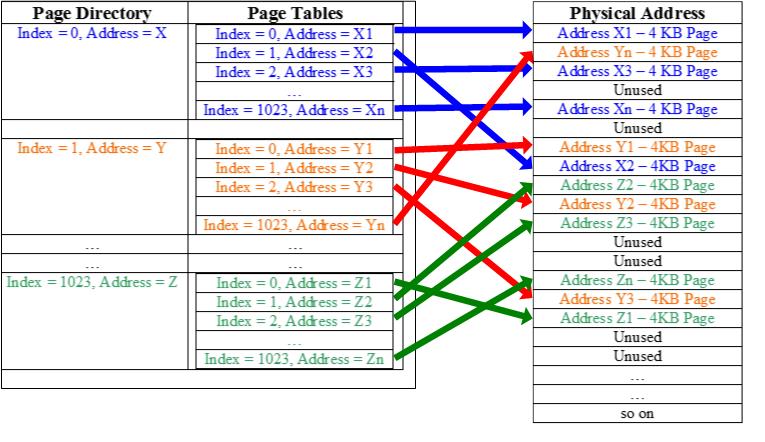
Each Page Directory Entry (or PDE) is 4 bytes in size and points to a Page Table. Similarly each Page Table Entry (or PTE) is 4 bytes and points to a physical address of a 4KB page. To store 1024 PDE each containing 1024 PTE, we will need a total memory of 4 x 1024 x 1024 bytes i.e. 4MB. Thus to divide the whole 4GB address space into 4 KB pages, we need 4 MB of memory.
As discussed above, the whole address space is divided in 4KB pages. So when a PDE or PTE is used, its upper 20 bits gives a 4KB page aligned address and lower 12 bits are used to store the page protection information and some other house-keeping information required by an OS for proper functioning. The upper 20 bits which represents the actual physical address are known as Page Frame Number (or PFN). Details on protection bits and other bits in the lower 12 bits can be found in here1.
Windows Page Table Management
In windows each process has its own Page Directory and Page Tables. Thus windows allocate 4 MB of this space per process. When a process is created, each entry in Page Directory contains physical address of a Page Table. The entries in the page table are either valid or invalid. Valid entries contain physical address of 4KB page allocated to the process. An invalid entry contains some special bits to mark it invalid and these entries are known as Invalid PTEs1. As the memory allocated by the process, these entries in Page Table are filled with the physical address of the allocated pages. You should remember one thing here that a process doesn’t know anything about physical memory and it only uses logical addresses. The details of which logical address corresponds to which physical address is managed transparently by Windows Memory manager and the processor. The address at which the page directory of a process is located in physical memory is referred to as Page Directory Base address. This Page Directory Base address is stored in a special CPU register called CR3 (on x86). On context switch, Windows loads the new value of CR3 to point to the new process’s Page Directory Base. This way each process gets its own division of the whole 4GB physical address space. Of course the total memory allocated at one time to all the process’s in a system cannot exceed the total amount of RAM + pagefile size but the scheme discussed above allows windows to give each process its own 4GB logical (or Virtual) address space. We call it Virtual Address space because even though the process has the whole 4GB address range available to it, it can only use the memory which is allocated to it. If a process tries to access an unallocated address, it will get an access violation because the PTE corresponding to that address points to an invalid value. Also the process can’t allocate more memory than what is available in the system. This method of separating logical memory from physical memory has lots of advantages. A process gets a linear 4GB address space so application programmers don’t have to worry about segments and all unlike in old DOS days. It also allows windows to run multiple processes and let them use physical memory on a machine without worrying about them stomping on each other’s address space. A logical address in one process will never point to the physical memory allocated to another process (unless they are using some sort of shared memory). Thus, one process can never read from or write to another process’s memory.
The translation from logical to physical address is done by the processor. A 32 bit logical address is divided in to three parts as shown below.
| 10 bits | 10 bits | 12 bits |
The processor loads the physical address of the page directory base stored in CR3. It then uses the upper 10 bits from the logical address as an index in the Page directory. This gives the processor a page directory entry (PDE) which points to a Page Table. The next 10 bits are used as an index in the page table. Using these 10 bits, it gets a page table entry (or PTE) which points to a 4KB physical page. The lowest 12 bits are used to address the individual bytes on a page.
Memory Protection
Windows provide memory protection to all the processes such that one process can’t access other process’s memory. This ensures smooth operation of multiple processes simultaneously. Windows ensure this protection by doing following:
- It only puts the physical address of allocated memory in PTE for a process. This ensures that the process’s gets an access violation if it tries to access an address which is not allocated.
- A rouge process may try to modify its page tables so that it can access the physical memory belonging to another process. Windows protect this kind of attacks by storing page tables in kernel address space. Recall from our earlier discussion that out of the 4GB logical address space given to a process, 2GB is given to user mode and 2GB is reserved for windows kernel. So a user mode application can not directly access or modify the page tables. Of course if a kernel mode driver wants to do that, it can do it because once you are in kernel mode, you virtually own the whole system. To understand this in more details, read the next section on Windows Logical memory layout below.
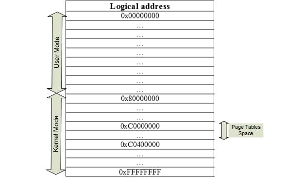
Windows Logical Memory Layout
Windows gives lower 2GB (or 3GB depending upon boot.ini switch) logical address space of a process to user mode and upper 2GB (or 1GB depending upon boot.ini switch) to Windows kernel. Out of the total kernel address space, it reserves addresses from 0xC0000000 to 0xC03FFFFF for Page Tables and Page Directory. Every process has its Page Tables located at the logical address 0xC0000000 and page directory located at logical address 0xC0300000. This logical memory arrangement is shown below:
You can use Windows kernel debugger kd or windbg to verify this (refer to !pte and !vtop debugger extenstions). The physical address to this page directory is stored in CR3. The 1024 addresses starting from 0xC0300000 represents Page Directory Entry (PDE). Each PDE contains a 4 byte physical address which points to a Page Table. Each Page Table has 1024 entries which either contains a physical address pointing to a physical page of 4KB or contains an invalid entry. This was also discussed above in the processor’s paging and Windows page table management section but repeated here for clarity sake.
So why does Windows use logical address 0xC000000000 to store the Page Tables and address 0xC0300000 to store page directory? The requirement for storing the page tables in memory is that a rouge user mode application should not be able to manipulate the page tables. Hence page tables should be in the kernel logical address space. Windows usually gives lower 2GB space to processes and reserves upper 2GB to kernel. But with a special boot.ini switch /3GB, it allows user mode process to access lower 3GB memory. 0xC0000000 is the next address after 3GB and so I guess that is why it is chosen for storing page directory and page tables. There are some other important aspects to page tables and page directory layout in memory. To understand that, let us look at how page tables and page directory is laid out. To make it easy to understand, I have drawn page tables for a fake process with relevant page table entries highlighted. Note that each index entry is 4 bytes in size. The numbers ending with ### represent the 4K aligned physical address.
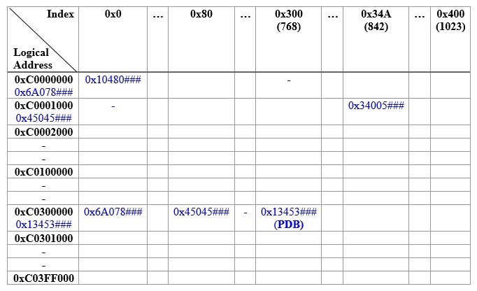
PDB represents the physical address of page directory base of the corresponding process i.e. it represents the physical address corresponding to logical address 0xC0300000 for that process. This value is also stored in CR3. Remember Windows can only use logical address to access any memory location including page directory, so to access page directory and page tables, it is necessary to put some self referencing entry in page directory. The physical address entries shown above will be different for each process but each process will have its PDB entry stored at index 0x300 of Page directory.
We will perform logical to physical address translation on 4 different addresses to see the significance of PDB entry, Page tables layout and how exactly the address translation works. The addresses which we will translate are 0x2034AC54, 0xC0000000, 0xC0300000, 0xC0300000[0x300] i.e. 0xC030C00. First address is a normal user mode logical address for a process, the second address is the first logical address of first page table in logical address space, third address is logical address of page directory base and fourth address is logical address of a special entry as you will see during translation. Assume CR3 points to a physical address 0x13453###. As pointed earlier, lower 12 bits are used to store page protection information and other information needed by an OS. These are out of the scope of our current discussion so I have shown them as ###. The upper 20 bits represents the Page Frame Number or PFN which is the physical address of a 4KB aligned page. The actual physical address corresponding to the PFN will be 0x13453000.
Let us do the translation of 0x2034AC54 now:
- 0x2034AC54 can be represented as 0010000000 1101001010 110001010100
- The upper 10 bits which are 0010000000 gives the index into page directory. Converting to hexadecimal, the upper 10 bits give a value of 0x080
- From CR3, we know the Page Directory is located at physical address 0x13453000 and from discussion above we also know that Page Directory is located at logical address 0xC0300000
- Thus 0xC0300000 [0x080] will give the address of page table which is P_PT. From the table above, we can see that this address is represented by page table at logical address 0xC00001000 (or physical address 0x45045000). Now we use next 10 bits i.e. 1101001010 (or 0x34A) to index into the page table.
- The address 0xC00001000 [0x34A] will give us the physical address of a 4KB page which is 0x34005000 from the table above.
- The number represented by lower 12 bits, which are 110001010100 (or 0xC54), is used to refer to the actual byte on the 4KB page located at 0x34005000. The final physical address corresponding to 0x2034AC54 comes out to be 0x34005C54
I will leave the address translation of other 3 addresses as an exercise to the reader. Once you do that translation, you will understand why the PDB entry is stored at index 0x300 in the table above and it causes processor to treat page directory as a page table during address translation. Also this translation will give you more information on why this particular layout was chosen by windows designers.
Reference
- Inside Windows 2000 by David A. Solomon & Mark E. Russinovich
- Undocumented Windows 2000 secrets by Sven B. Schreiber
This posting is provided “AS IS” with no warranties and confers no rights.